Servo control
Contents
This chapter is all about servomechanisms, servos for short. You will learn:
- What is a servo? How does it work?
- How to connect a servo?
- How to control a servo?
- Different types of servos
Theory
A servomechanism (servo) is a feedback system that uses a closed-loop controller to set and actively adjust its position and/or velocity as an actuator1, 2. There are many types of servos i.e., hydraulic, pneumatic, electric 1. In this tutorial, we shall focus on typical positional rotation DC motor servos, often used in RC control models.
Let’s quickly decipher the definition to fit our context:
- servo does rotate
- servo does keep its position
- servo can be controller with a microcontroller
Internally, a servo is an effector (here: a DC motor) wrapped with electronics that read and control its position. To read a position you need some sort of encoder. You also need a control mechanism/circuitry to read the position and correct it. Often, it’s a microcontroller with custom software, usually a PID controller. Finally, the servo needs to actuate in the real world. 5V/20mA is barely enough to light up an LED. The DC servo comes with an H-bridge to control position and power in the DC motor. The servo also may need gears (gearbox) to increase output torque. All of it comes in a small and usually affordable package!
Hopefully, you bought SG92(R) servo. It’s a small servo that offers a decent torque in a small casing. There are three wire leads: brown, red, orange. Colors may vary in tinge. The middle one, the red one is a positive power supply. You’ll connect 5V there. The brown one is GND. The orange one is PWM signal, which controls the position of the servo. Make sure you connect it to PB1 pin. The pinout of the servo is pretty smart. 5V lead in the middle effectively prevents you from applying wrong polarity. If you connect the PWM lead to GND by mistake, nothing will happen! Of course, try always to connect your hardware correctly.
| Servo | Arduino Nano | Atmega Pinout |
|---|---|---|
| Orange | D9 | PB1 |
| Red | 5V | N/A |
| Brown | GND | N/A |
There are many tutorials in the Web. You can google them or simply use one of the below links:
Now, how to control it?
- 50Hz PWM signal
- 5%-10% duty cycle, to control its position between its maximum ranges (often 0 to 180deg)3. There are lots of variations on it4. From my experience, this is a good approximation but still it’s better to calibrate the values on your own.
- Power supply and GND are also welcomed :)
Servo library
Arduino IDE comes with Servo library included5. The library uses 16-bit timer to provide precise timing to control servos. The library can control up to 60 servos, depending on a microcontroller you use.
There is an official Arduino Servo tutorial if you need a different perspective on basics6.
Let’s take a look at an example (source: Arduino Servo library: Hello World!):
#include <Servo.h>

static constexpr const uint8_t SERVO_PIN {9};
static Servo servo;

void setup() {
  servo.attach(SERVO_PIN);
}

void loop() {
  for (uint8_t angle = 0; angle <= 180; angle += 45) {
    servo.write(angle);
    delay(1000);
  }
}
The first line #include <Servo.h> includes the Servo library. It comes with Arduino IDE so you
don’t need to install anything. The servo device uses pin #9 as suggested in the pinout table above.
Moreover, you need to create an object of type Servo: static Servo servo;.
The next step is to simply connect the servo object (software) with your more tangible servo, the hardware on pin 9: servo.attach(SERVO_PIN); // SERVO_PIN=9.
Finally, we want to use the servo, so it’s business time. The logic shall move servo handle/hook/rudder
in increments of 45 degrees. To issue a command and set a desired position, you need to run servo.
write(angle); command. Don’t forget about a reasonable delay so the servo can make a move.
Once you compile the software and deploy it to your microcontroller, you’ll observe how the servo moves. Congratulations! It’s working! It’s alive!

The servo moves but its manual mentions 0-180 degree range. My servo certainly doesn’t meet the specification, at least for now. You need to calibrate it. Luckily, the library allows you to attach a servo and defining a pulse width for PWM signal. Remember? 5%-10% duty cycle. Let’s involve some trial and error then…
Let’s take a look at another example (source: Arduino Servo Calibration):
#include <Servo.h>
#include <ArduinoJson.h>

static constexpr const uint8_t SERVO_PIN {9};
static Servo servo;

static JsonDocument json;

inline void applyServoPosition(uint8_t angle);

void setup() {
  Serial.begin(115200);
  servo.attach(SERVO_PIN, 540, 2540);       // calibrated servo
  servo.write(0);

  while (!Serial);
}

void loop() {
  if (Serial.available() > 0) {
    auto error = deserializeJson(json, Serial);
    if (!error) {
      applyServoPosition(
        static_cast<uint8_t>(json["pos"])); // contract: pos shall be in range 0-180
      serializeJson(json, Serial);
      Serial.println();
    }
  }
}

void applyServoPosition(uint8_t angle) {
  servo.write(angle);
}
The example employs ArduinoJson and Serial to let you control the servo with your Serial Monitor.
The calibration for such a servo can be complicated task if you need to perform extra precise
operations (see: Metrology). It can be also very simple if
you need it for non-critical applications. As most of us love taking a simple route, let’s
play with this line: servo.attach(SERVO_PIN, 540, 2540).
How did I come up with it? Well, you start with the default values and you issue a command:
{"pos":0}
in Serial Monitor. This is the default state. Connect a handle/needle/rudder as parallel to the servo case as possible. Then, If you cannot achieve parallelism regardless of the handle rotation, you need to adjust the timings in software. The first value 540 is the minimum (by default Arduino uses: 544) that corresponds to 0degree position. You subtract the value if the parallelism is overshot, or add if the handle goes back a bit too much. You take a similar approach for the next position:
{"pos":180}
You issue this command in the Serial Monitor. By default, Arduino assumes the max value to 2400. My handle never reached real 180 degree movement so I needed to increase it up to 2540. The magic values you enter are microseconds (1us=10-6s). The library uses 16-bit timer to generate interrupts at frequency of 2MHz (16MHz CPU freq, and prescaler=8), which translates to *0,0000005s = 0.5us` resolution. This is how often the library processes an ISR procedure to mimic PWM and apply correct duty cycle for up to 60 servos! Science? Magic? No, it’s engineering! If you are interested how it’s really implemented, I suggest you take a look at the original source code7.
Assuming you use Cytron’s Nano board, you also should see how the D9 LED changes its brightness.
This is of course a sign of PWM, although implemented with software means. How does a waveform
look like? An oscilloscope can provide some details:

Figure: Oscilloscope - servo at 0 deg, zoom out

Figure: Oscilloscope - servo at 0 deg, zoom in, 500us grid resolution
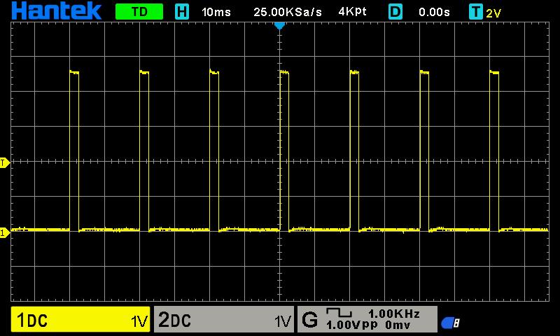
Figure: Oscilloscope - servo at 180 deg, zoom out
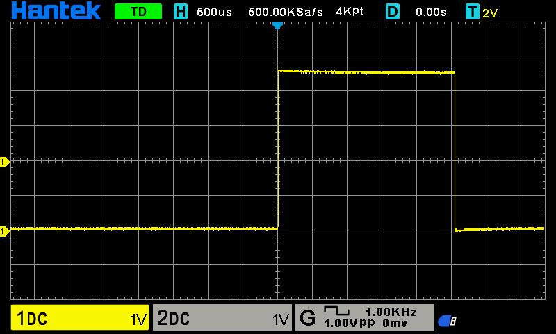
Figure: Oscilloscope - servo at 180 deg, zoom in, 500us grid resolution
Take a look at any zoom-out chart, with 10ms resolution. The diagram is showing peaks at 20ms intervals, which translates to 50Hz PWM frequency. The zoom-in diagram is scaled in 500us resolution. You can see how wide the peak is, which in our case is slightly more than 500us and 2500us, just as we programmed it! Isn’t it wonderful?
Alright, we’re done with the library. Go ahead and check the documentation or simply see the library header for details8. What if you don’t want to trigger 2 million interrupts every second? Well, this brings us back to a hardware-based solution. Yes, you guessed it. It’s time to generate hardware PWM at 50Hz and use it as the output.
Hardware-based servo control
Actually, we did exercise this bit earlier in the tutorial. Remember PWM section in Analog input, Pulse Width Modulation chapter? Go ahead!
You can use up to two servos with the 16-bit timer in Atmega328p. It’s not much. Remember, you can always design your own board that controls many more servos. Really, it’s just a question of requirements and some engineering decisions. Arduino Servo library is a very good one of amateur projects as it lowers an entry threshold to get started with. With more advanced projects you will know when to make the right decisions to balance costs vs complexity vs timing requirements (vs other parameters). This is engineering :). Simply, delivering good tradeoffs.
Ok. That’s enough of coaching. Let’s take a look at the code (source: Servo - 16bit timer, Hello World:
class Servo {
  public:
  enum class SERVO_SELECTOR {
    SERVO_1,
    SERVO_2
  };
  static inline void setAngle(SERVO_SELECTOR servo, uint8_t angle) {
    uint16_t dutyCycle = map(angle, 0, 180, 540, 2540);

    switch (servo) {
      case SERVO_SELECTOR::SERVO_1:
        OCR1A = dutyCycle;
        break;
      case SERVO_SELECTOR::SERVO_2:
        OCR1B = dutyCycle;      // unused: COM1B1 is disabled
        break;
      default:
        break;
    }
  }
};
void setup() {
  DDRB |= (1<<PB1); // Set PB1 as output
  /*
      Enable PWM on PIN PB1/Arduin D9

      CPU CLK, fclk_I/O = 16,000,000
      Timer: Phase Correct PWM, see 15.9.4 Phase Correct PWM Mode in Datasheet
      Formula: fOCnxPCPWM = fclk_I/O / {2* N * TOP}
      fOCnxPCPWM=50Hz
      Prescaler: N=8
      TOP = fclk_I/O / {2 * N * fOCnxPCPWM}

      TOP=ICR1=20000
  */
  TCCR1A = (1<<COM1A1)   // PB1 as PWM, see the pinout
      | (1<<WGM11);      // phase correct PWM, TOP=ICR1
  TCCR1B = (1 << WGM13)
      | (1 << CS11);     // prescaler 8
  ICR1 = 20000;          // 50Hz
}

void loop() {
  for (uint8_t angle = 0; angle <= 180; angle += 45) {
    Servo::setAngle(Servo::SERVO_SELECTOR::SERVO_1, angle);
    delay(1000);
  }
}
Well, this is straightforward, isn’t it? First thing you need to do is to set up PWM: 1) make
PB1 pin as output, 2) compute parameters for a given timer (here Phase Correct PWM), 3) apply the
computed values, including ICR (Input Capture Register, say ‘the frequency register’),
4) set PB1/COM1A1 pin as output, 5) use the timer OCR1A/OCR1B registries.
The whole setup() function is about setting up the timer. Servo::setAngle() does two things:
1) converts angles to microseconds/ticks for the given timer, 2) applies the value.
The application does the very same thing as the first Hello World example. This time, you did it solely with hardware. Good job!
Summary
You should be pretty comfortable with controlling servos by now. There are also different servos, some people names them digital. The difference is you don’t need PWM to control them, you need UART or effectively any specified communication protocol (check servo specs!). Usually this kind of a servo is more expensive as it provides additional feedback information such as position, power use and allow using it as a regular motor (continuously rather than just angle control).
That’s it! Let’s integrate the knowledge you gained throughout the course to finally build a robot!