Analog input, Pulse Width Modulation
Contents
This chapter shall introduce you to a read and write analog inputs/outputs. Digital electronics and analog values? Yes, exactly!
Analog input
Atmega328p comes with a 10-bit Analog-to-Digital-Converter, ADC for short. Note the singular form of ADC. There is just one ADC, yet supported in multiple Atmega leads. This can be done by simply multiplexing the signal. It means the circuit iterates over ADC-ready pins and reads values sequentially, one pin after another. The diagram represents the circuit design (source 1):
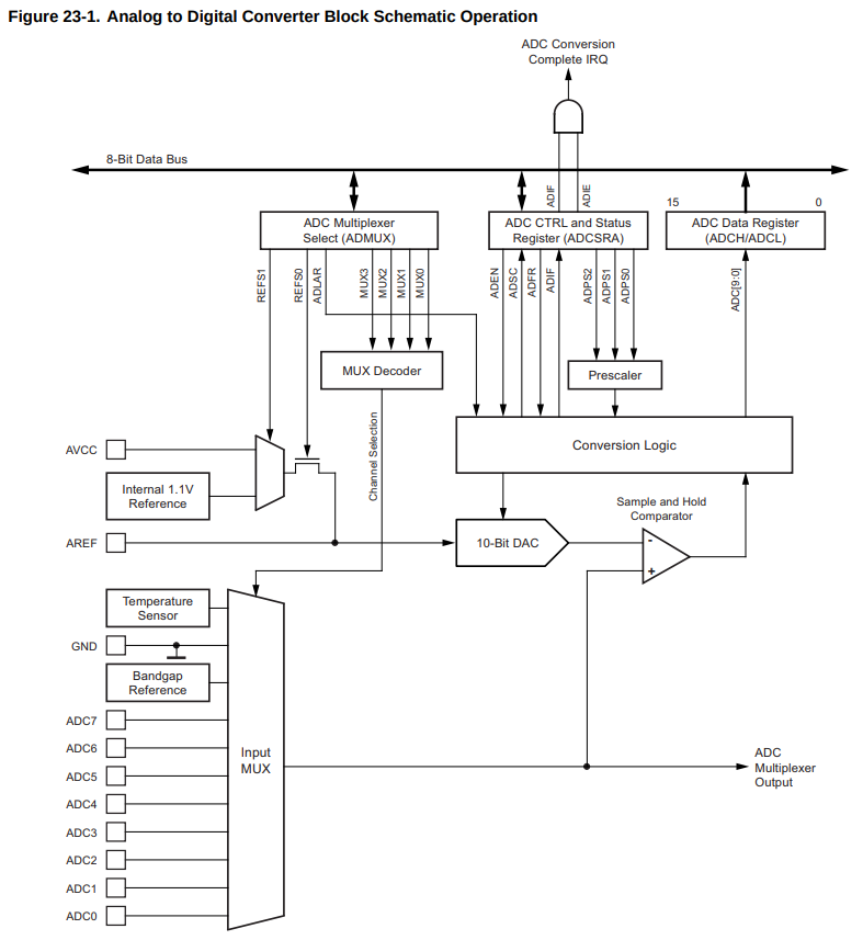
You need one more bit to understand basics of ADC. So far we know it’s a 10-bit ADC, which means 0-1023 values, and a multiplexer that we need to handle in one way or another. Good, but still we need a reference point, don’t we?
You have several options:
- provide your own reference voltage
- use Vcc as a reference (see
AVCCin the diagram) - use built-in 1.1V reference (you can change it with
analogReference()function, or settingADMUX |= (1<<REFS1) | 1<<REFS0))
There is also a limit on how fast you can measure the voltage: 10kHz according to
analogRead() documentation.
You can also use ADC as a comparator, which can become handy to implement one of the proposed robot features.
Alright, let’s take a look at some code. You need to build a circuit like the one below. All you need is your board, some wires and a photoresistor.
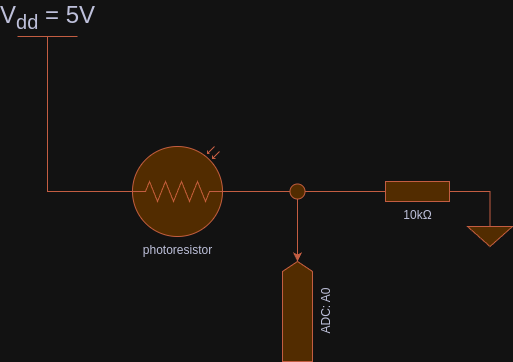
[!NOTE] If you take a closer look at the circuit, you notice it’s a voltage divider! You can control ADC value at-rest by modifying the resistor value. Try it yourself with 1k, 10k and 100k resistors.
Use the following Arduino code (source - Analog Read with Serial Monitor):
static constexpr const uint8_t ANALOG_PIN_PHOTORESISTOR = A0;

static uint16_t photoresistorValue = 0;

void setup() {
  Serial.begin(115200);
  while (!Serial);
}

void loop() {
  photoresistorValue = analogRead(ANALOG_PIN_PHOTORESISTOR);

  Serial.print("photoresistor ADC (0-1023) = ");
  Serial.println(photoresistorValue);

  delay(50);
}
Let’s dismiss explanation for Serial prefixed calls. It’s UART and shall be formally introduced
in the next chapter. All you need to know about it is UART can transfer data onto your PC and
display it in a serial monitor (in Arduino IDE: Tools -> Serial Monitor, make sure baud is set to 115200):
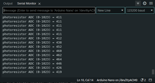
Use a flashlight or a phone LED to shed a beam of light onto the photoresistor. You’ll see how the values change. By default, if no light reaches the photoresistor, it’s effectively a break in a circuit, which translates to high resistance (think megaohms). On the other hand, the brighter the area, the less resistance can be observed.
From the code perspective, Arduino offers a function called analogRead(<<ANALOG PIN>>).
It returns a value between 0-1023, that corresponds to 0-5V in the real world. It’s up to you, how you map it.
You can, obviously, use a function map() to map things. Say you want convert ADC value into a PWM value 0-1023 -> 0-255,
you can type uint8_t result = map(<<adc value>>, 0, 1023, 0, 255);
Note the delay() at the end of processing. It’s linked with how multiplexer really works. It takes
time to iterate over each analog pin. Still, analogRead() is pretty good if you simply want to get
an analog value quickly.
How would Atmega code look like? Well, it’s more complicated than one simply function call (source Analog Read - Registers):
static uint16_t photoresistorValue = 0;

void setup() {
  Serial.begin(115200);
  while (!Serial);

  ADCSRA = (1 << ADEN)  // enable ADC
    | ((1 << ADPS2)
    | (1 << ADPS1)
    | (1 << ADPS0));     // prescaler 128
  ADMUX = (1 << REFS0); // MUX3..0 bits are set to 0, which is ADC0/PC0/A0 pin
}

void loop() {
  ADCSRA |= (1 << ADSC);            // start ADC convertion
  while (!(ADCSRA & (1 << ADIF)));  // wait until ADC completes its job
  photoresistorValue = ADC;         // provide ADC value present on A0 pin

  Serial.print("photoresistor ADC (0-1023) = ");
  Serial.println(photoresistorValue);

  delay(50);
}
There are 3 registers you need play with (see 23.9 Register Description 1):
ADCSRA- ADC Control and Status register, enables/disables ADC, triggers a conversion and sets up basic parametersADMUX- ADC Multiplexer Selection Registers - allows choosing a given channel in an ADC multiplexerADC- combined result ofADCH(high register) andADCL(low register) in 16bit variable - expect 10-bit value
So the first step is to enable ADC hardware and set up a prescaler to reduce MUX processing speed
(16MHz, default clock in your board) by dividing it by 128, so the hardware can really measure a
value. Then, you choose a channel from which you intend to read. Finally, you perform a blocking wait
while (!(ADCSRA & (1 << ADIF))) until the channel is ready to provide an analog value measured on a pin.
Of course, if you remember your interrupt tutorial, you can use an interrupt here as well.
You need to implement an ISR(ADC_vect) and start ADC in an interrupt mode by enabling ADCSRA |= 1 << ADIE bit.
Of course, you cannot forget about enabling global interrupts sei()
(source: Analog Read with Interrupt):
volatile uint16_t photoresistorValue = 0;

void setup() {
  Serial.begin(115200);
  while (!Serial);

  ADCSRA = (1 << ADEN)  // enable ADC
    | ((1 << ADPS2)
    | (1 << ADPS1)
    | (1 << ADPS0))     // prescaler 128
    | (1 << ADIE);      // enable interrupts

  ADMUX = (1 << REFS0); // MUX3..0 bits are set to 0, which is ADC0/PC0/A0 pin
  ADCSRA |= 1 << ADSC;  // start ADC, handle a response in the ISR routine
  sei();
}

void loop() {
  Serial.print("photoresistor ADC (0-1023) = ");
  Serial.println(photoresistorValue);

  delay(50);
}

ISR(ADC_vect) {
  photoresistorValue = ADC;
  ADCSRA |= 1 << ADSC;      // run ADC/ch:adc0 immediately again
}
I suggest you to review documentation in details if you need to provide accurate measurements. For the sake of this tutorial, a coarse value is enough. The documentation introduces you to things such as ADC Noise canceller and available techniques, ADC accuracy and measurement errors etc.
Analog output - PWM
Let’s face it, you cannot have an analog output without a DAC (Digital to Analog Converter)… You can get a really good approximation, though!
There are a few ways you can think about it. Say you want your LED emit light at half of it’s luminosity. Naturally, you may want to run an LED at half of your voltage, say 1.5V. You can construct a voltage divider to get 1.5V. It’s far from ideal if you want to dynamically control a brightness of your LED or control an electric motor. In a case of the electric motor, your circuit would dissipate lots of energy on simply making sure you reach desire voltage.
So what can we do? Well, you can turn off and on your 5V signal very fast. So fast that you won’t even notice that LED is off or motor is not supplied with power. How fast, well - it depends. For an LED 25Hz should be enough if you recall old school TVs. You don’t really see images changing, although the refresh rate is roughly 24-25Hz. For DC motors, I’d say anything above 20kHz is good enough so you don’t hear anything (20kHZ is a max frequency a human ear can hear). Obviously, it also depends on the hardware you plan to use…
If you measure voltage while quickly toggling pin state, you’ll see a square-like signal, a square wave. You achieve it by simply turning on and off the pin. Say, you want your LED emit light for 0.1 second and rest for 0.9s. Then, repeat! Congratulations, that’s all about PWM! If your period takes one second to implement and the LED is active only for 10% of that time, it is 10% duty cycle. Duty cycle is a period in which your effector performs work, in this case - it emits light.
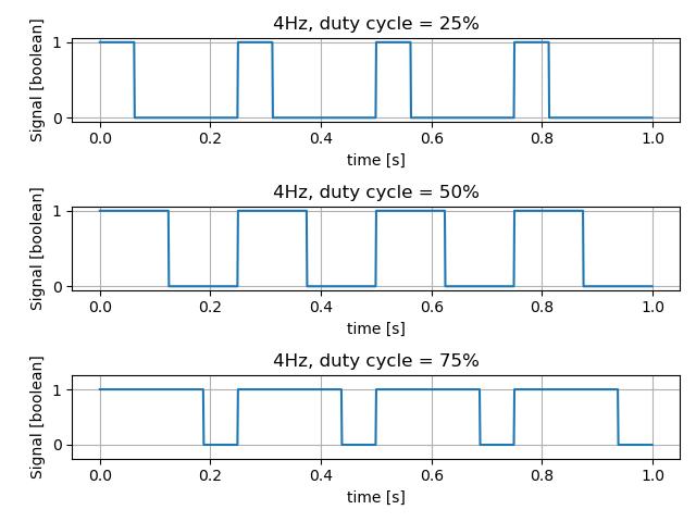
Take a look at this diagram to fully understand how it works:
 .
.
The diagram presents different duty cycle at 4Hz frequency (or 0.25s period). 25% duty cycle means the signal is active only for 1/4 of period. Similarly, 50% duty cycle, means it’s active for half the time period. If you run your duty cycle at 100%, effectively you turned your signal into a turn on/off switch.
The amplitude is of course Vcc=5V. So on average, 25% of 5V gives 1.25V. There is also a more fancy formula to compute it:
\[x_{avg} = \frac{1}{T} \int_{t_0}^{t_0+T} u(t)^2 \,dt\]If you run the integral against the square waveform function and simplify the results, you’ll get a simple equation, in Volts:
\[U_{avg} = d \cdot U_{max.amplitude}\]where d is duty cycle i.e., d=0.25 for 25% duty cycle.
I almost forgot… The phenomenon is called Pulse Width Modulation (PWM in short). Hopefully, you see why. Take a look at the diagram - duty cycle is represented by width. More the width, greater the average signal/power/voltage/anything, the wider is the pulse.
Now, let’s implement a naive PWM example, by hand (source PWM - Naive implementation).
static constexpr const uint8_t DUTY_CYCLE = 10;

static constexpr const int PERIOD_MS = 10;                              // 1/0.01s = 100Hz
static constexpr const int ON_PERIOD_MS = PERIOD_MS * DUTY_CYCLE / 100; // round
static constexpr const int OFF_PERIOD_MS = PERIOD_MS - ON_PERIOD_MS;

static constexpr const uint8_t LED_PIN = LED_BUILTIN;


void setup() {
  pinMode(LED_PIN, OUTPUT);
}

void loop() {
  digitalWrite(LED_PIN, HIGH);
  delay(ON_PERIOD_MS);

  digitalWrite(LED_PIN, LOW);
  delay(OFF_PERIOD_MS);
}
Go and play with it, modify DUTY_CYCLE to 10, 20, 30… and so on. Observe your LED
(the built one, or any other you are willing to connect).
You can see that LED has different brightness depending on the value.
The loop() portion simply turns on and off the LED. In the given example, PWM works at roughly 100Hz
and duty cycle of 10%. Your LED should be very dim. It’s roughly 100Hz because it takes some CPU cycles to call each
function digitalWrite, delay. Still, it’s a good 100Hz approximation. You can do better though! Keep reading!
PWM is so common that probably all microcontrollers available on the market provide hardware support for PWM. Arduino Nano/Atmega328p is no different! Let’s translate the code to more Arduino friendly form (source: Arduino - analogWrite). Make sure you connect your own LED to PIN 6, or simply use one that comes with your Cytron’s board:
static constexpr const uint8_t DUTY_CYCLE = 10;  // 10% duty cycle
static constexpr const uint8_t LED_PIN = 6;      // PWM-ready pins: 3, 5, 6, 9, 10, 11

static constexpr const uint8_t PWM_VALUE = UINT8_MAX * DUTY_CYCLE / 100;

void setup() {
  pinMode(LED_PIN, OUTPUT);
  analogWrite(LED_PIN, PWM_VALUE);
}

void loop() {
  // nothing to do
}
You can clearly see a new function here: analogWrite(<<pin>>, <<pwm value, 0..255>>) 2. The
function uses hardware PWM module to generate a square wave signal at roughly 500Hz or ~1kHz,
depending on pin you want to use. You can either refer to Arduino documentation or simply take a look
at your board to see which pins support PWM (usually marked with ~ character).
It should be enough for most of your LED-cases. What if you want to use other frequencies? Atmega comes with a set of timers: 8-bit and 16-bit timers that let you customize your PWM pin (or count signals etc.). See 14. 8-bit Timer/Counter0 with PWM and 17. 8-bit Timer/Counter2 with PWM and Asynchronous Operation for more details on 8-bit timers 1.
Let’s say you want to run your PWM at exactly 50Hz… Things get trickier, don’t they? Well, for such a use case we need to address some of the Atmega registers and the 16-bit timer! See 15. 16-bit Timer/Counter1 with PWM for more details 1.
There are two Arduino pins that support the 16-bit timer: PB1/D9 and PB2/D10, also known OC1A
and OC1B correspondingly. Connect your LED to to PB1/D9. Remember about a resistor (at least 220Ohm)!
Source: Arduino - Phase Correct PWM:
static constexpr const uint8_t DUTY_CYCLE = 10;  // 10% duty cycle

void setup() {
  DDRB |= (1<<PB1); // Set PB1 as output
  /*
      Enable PWM on PIN PB1/Arduin D9

      CPU CLK, fclk_I/O = 16,000,000
      Timer: Phase Correct PWM, see 15.9.4 Phase Correct PWM Mode in Datasheet
      Formula: fOCnxPCPWM = fclk_I/O / {2* N * TOP}
      fOCnxPCPWM=50Hz
      Prescaler: N=8
      TOP = fclk_I/O / {2 * N * fOCnxPCPWM}

      TOP=ICR1=20000
  */
  TCCR1A = (1<<COM1A1)   // PB1 as PWM, see the pinout
      | (1<<WGM11);      // phase correct PWM, TOP=ICR1
  TCCR1B = (1 << WGM13)
      | (1 << CS11);     // prescaler 8
  ICR1 = 20000;

  OCR1A = ICR1 * DUTY_CYCLE / 100;  // PWM values are in range 0..ICR1
}

void loop() {
  // nothing to do
}
Wait, what? Exactly! Some math, bit shifts and dark magic… Yes, I know the feeling. That’s why I use Arduino libs if I don’t need to handle any specific use cases.
First of all, 16-bit timer comes with several available modes: Normal Mode, CTC (Clear Timer on Compare match), Fast PWM, Phase Correct PWM, Phase and Frequency Correct PWM. Make yourself familiar with the documentation in chapter 15. 16-bit Timer/Counter1 with PWM 1.
I chose the Phase Correct PWM (see 15.9.4 Phase Correct PWM Mode 1) because this particular mode is a good choice for motors, quote:
“However, due to the symmetric feature of the dual-slope PWM modes, these modes are preferred for motor control applications.”
To set up precisely 50Hz, you need to follow the formula:
\[f_{OCnxPCPWM} = \frac {f_{clk_I/O}} {2 \cdot N \cdot TOP}\]where fOCnxPCPWM is frequency in Hz, N - prescaler, and TOP either ICR1 (Input Capture Register) or OCR1A/OCR1B (Output Capture Register), depending on your timer configuration.
By default, Arduino boards work at 16MHz frequency, which is 16,000,000Hz. Let’s transform the formula:
\[TOP = \frac {f_{clk_I/O}} {2 \cdot N \cdot f_{OCnxPCPWM}} = \frac {16000000} {2 \cdot 8 \cdot 50} = 20000\]You can apply a different prescaler i.e. N=64, which results in TOP=2500.
The resolution of a timer is a bit narrower. That can still be perfectly fine with your use case. It’s up to you, freedom!
Please, compare the code snippet with the table Table 15-5. Waveform Generation Mode Bit Description(1) 1. I chose a timer #10 that clears on ICR1, which means no “internal counter increments” for the timer. The hardware goes from BOTTOM to TOP/ICR1 and then back from TOP/ICR1 to BOTTOM. I am more interested in changing duty cycle rather than the frequency. If you want to generate sounds, you might as well choose timer #11, and keep duty cycle constant (so your music stays at the same level). Yet another engineering decision.
Ok, so we have prescaler N=8, which translates to TCCR1B |= (1 << CS11) (see table Table 15-6. Clock Select Bit Description 1),
and ICR1=20000. To set up the Phase Correct PWM, you need to modify two registers:
TCCR1A |= 1 << WGM11 and TCCR1B |= 1<< WGM13. Finally, you want to
enable PWM on the PB1 pin, here also known as COM1A1 by setting bit TCCR1A |= 1 << COM1A1 (see
table Table 15-4. Compare Output Mode, Phase Correct and Phase and Frequency Correct PWM(1)). Don’t
forget about the direction registry DDRB |= (1<<PB1).
Finally, you want to set duty cycle. Remember, ICR1 is your max value, you simply compute your 10% duty cycle OCR1A = ICR1 * DUTY_CYCLE / 100.
Yes, we’re done with it! Congratulations!
You probably have a question: why 50Hz? Well, that’s a secret! Check the servo control chapter ;)!
Going back to the theory. PWM does not provide voltage control. It can only control the overall power output but still within zeros and ones. If you inspect your circuit to an oscilloscope, you’ll see a pretty nice square waveform. It’s nothing like a flatline with a steady voltage. If this is really what you want to achieve, you can implement an RC circuit or even RLC one 34. You need to be familiar with analog electronics, which is magic in itself. The easiest way both money and time wise is to buy an external DAC converter such as this one MCP4725.
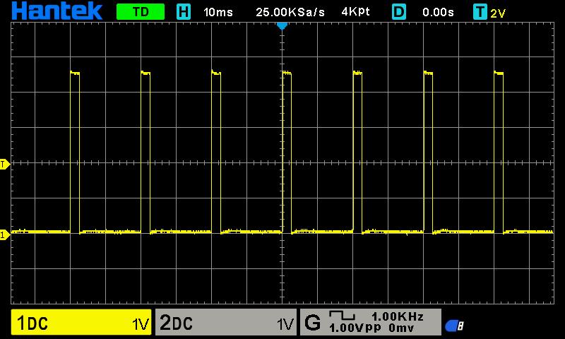
Figure: PWM example, 12.75% duty cycle @50Hz.